Snow-Meep
A light-up snowman soldering badge kit for events and workshops.
Overview · Tutorial · Common Problems
Overview
Tutorial
Step 1 - Your kit
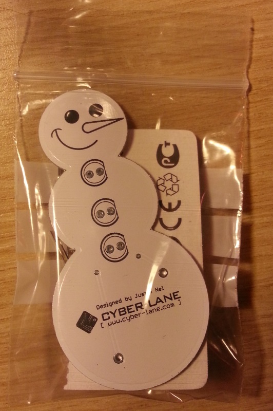
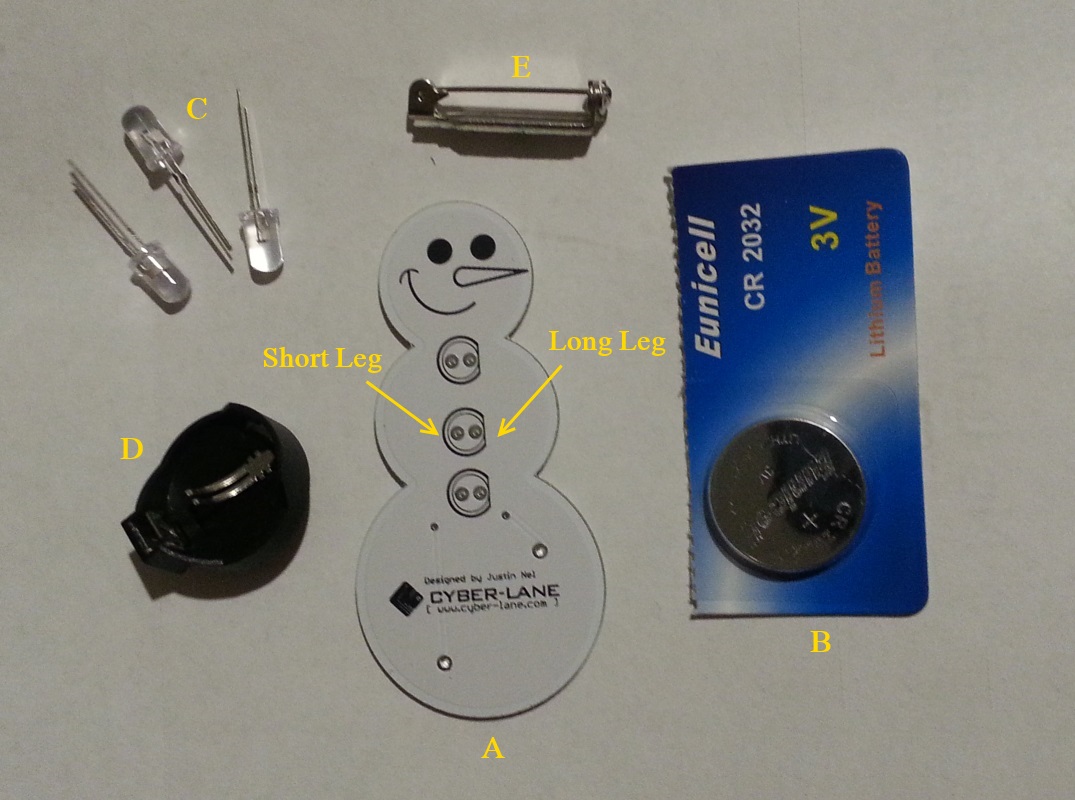
You should have a kit which looks pretty similar to this
Each kit comes with the following pieces:
A) Your badge, which is a Printed Circuit Board (PCB)
B) A CR2032 coincell battery
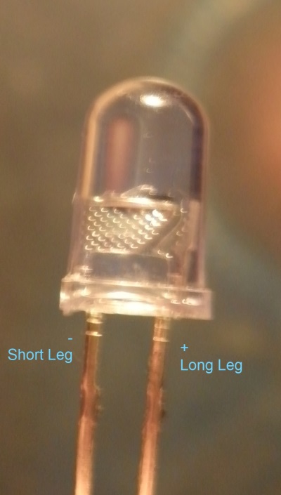
C) 3x LEDs (these will be the ‘buttons’) - one leg is longer than the other: the longer leg goes to the right hand side, where the circle has a flat line and the shorter leg goes into the other to the left.
D) A battery holder
E) A sticky pin
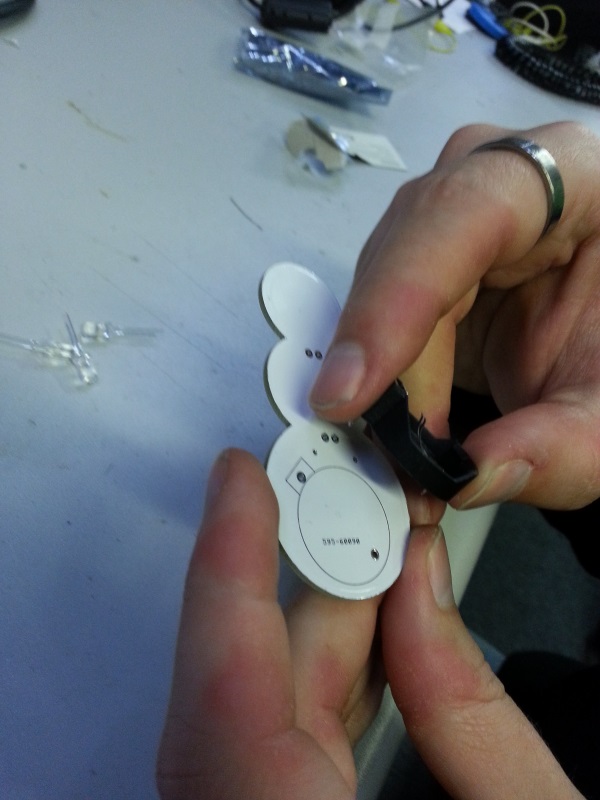
Step 2 - The battery holder
You begin by placing the battery holder into the holes on the back of the badge. Please take note to the shape of battery holder and the outline. Ensure that you place the square edge of the battery holder to the top left where the outline matches.
Carefully turn the badge over, and make use of a pencil or something of similar height to rest the the head of the snowman on, so you are able to solder the battery holder on without it wobbling.
For detailed instructions on how to solder, please visit this link (coming soon).
Once you have soldered in the battery holder, it should look something similar to this:
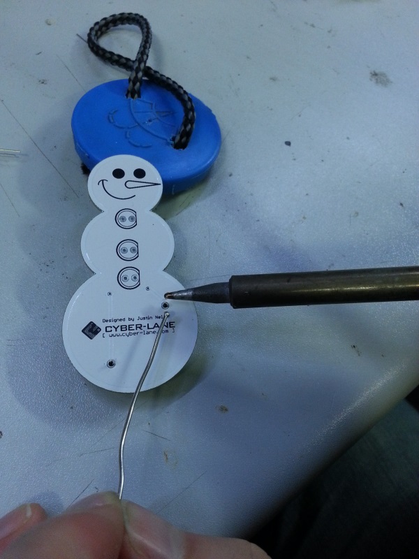
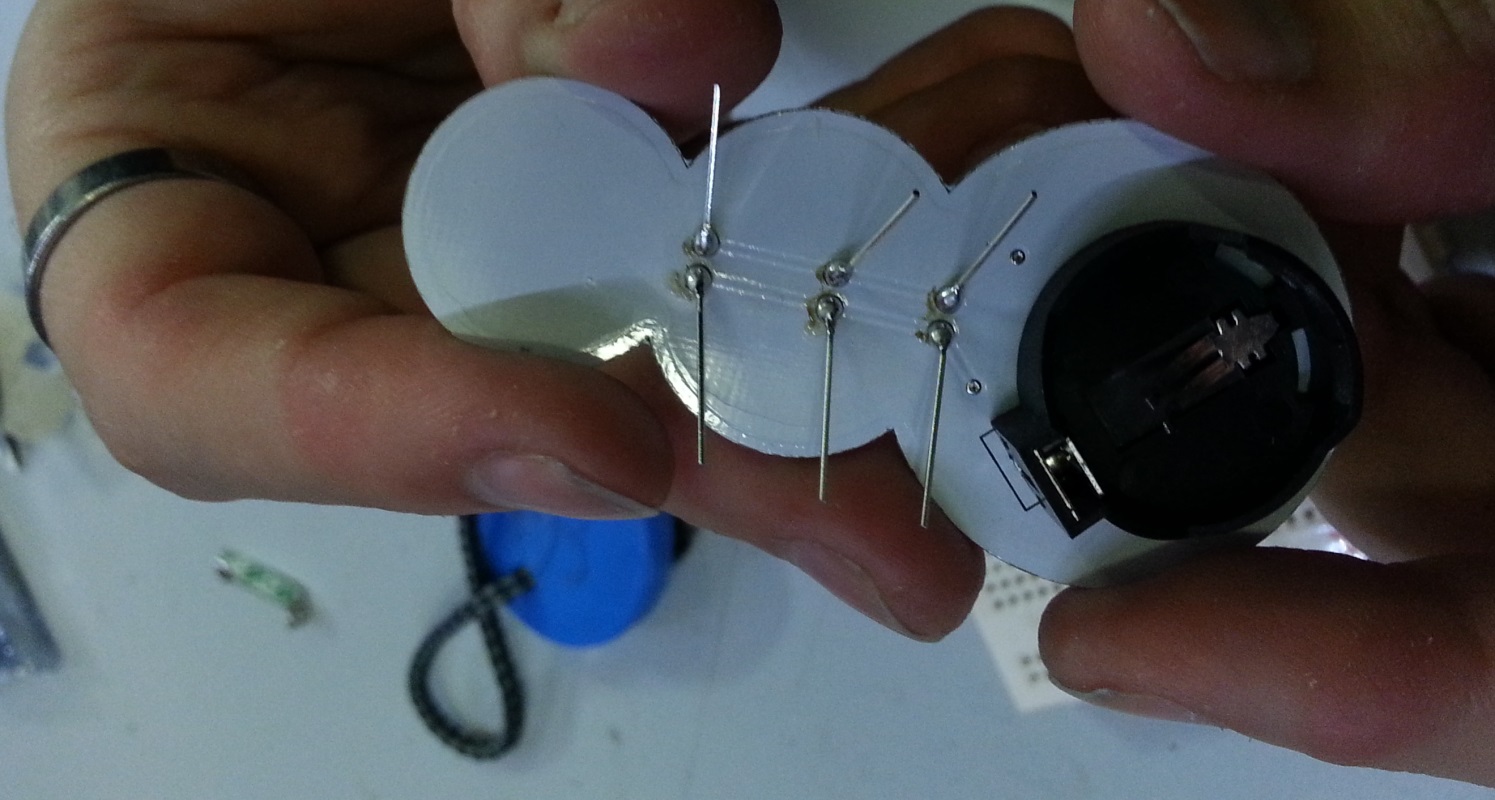
Step 3 - The LED buttons
As mentioned earlier on, the LEDs have one leg longer than the other. The longer leg goes into the right hand side where the black circle is flat, and the shorter leg goes into where it is round on the left.
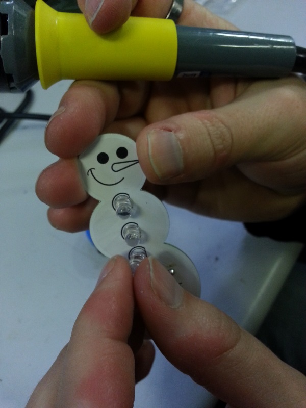
Carefully turn the badge over with your finger keeping the LEDs in place.
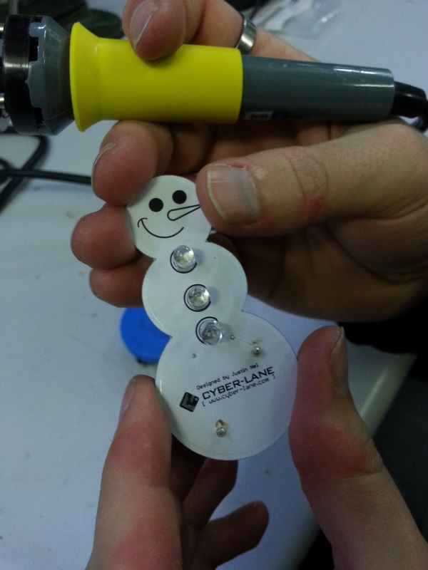
Now bend the LED legs outwards as seen in the photo below, and begin to solder them one by one.
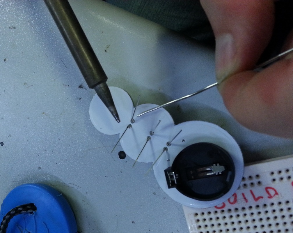
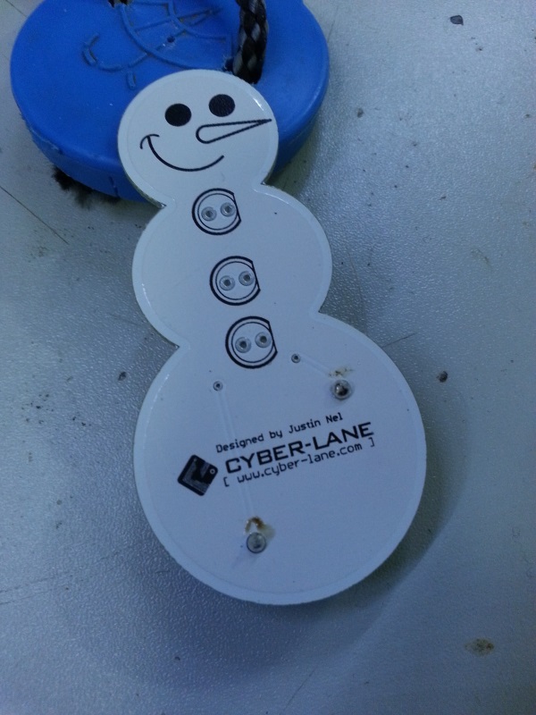
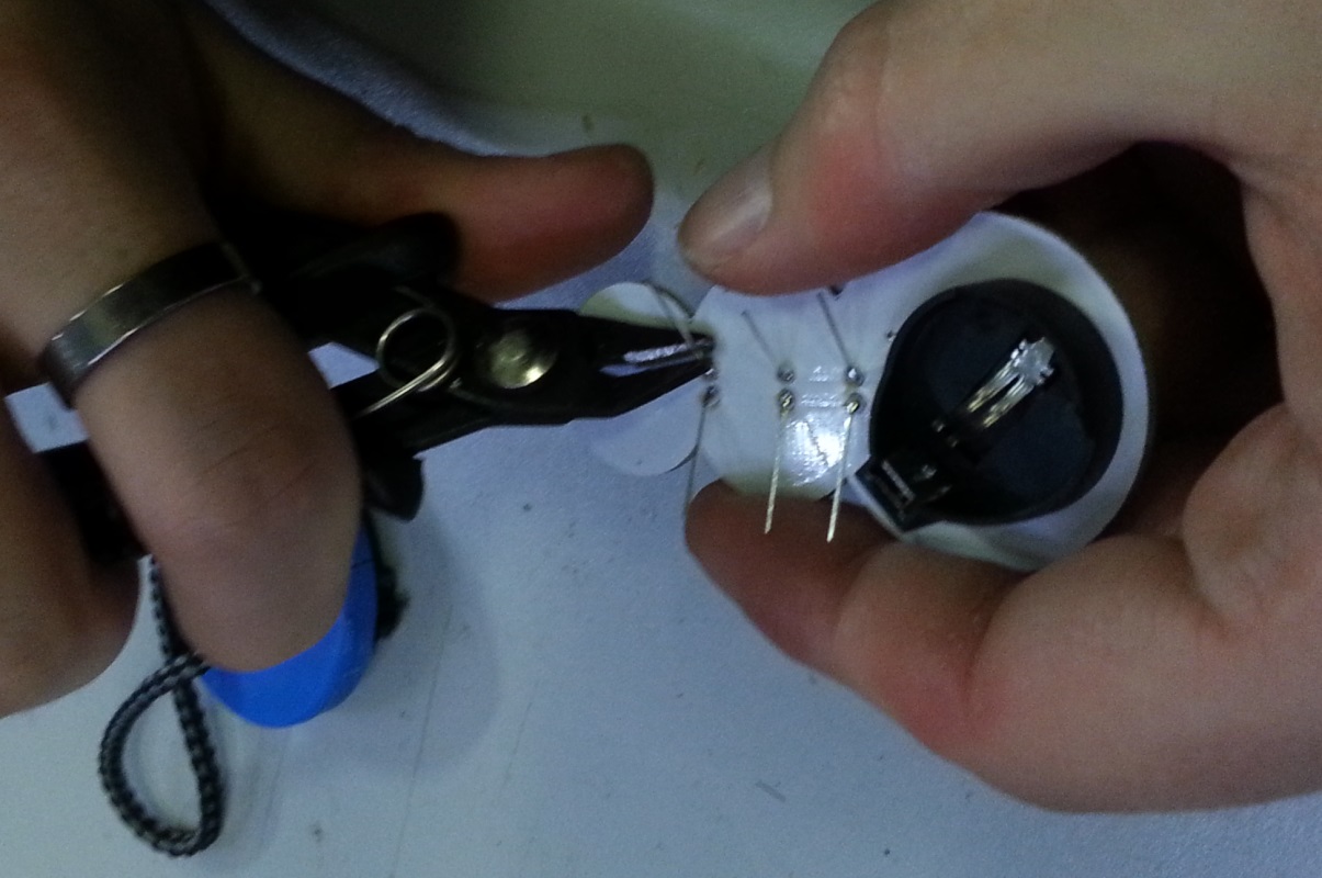
When they are all soldered, they should look something like this:
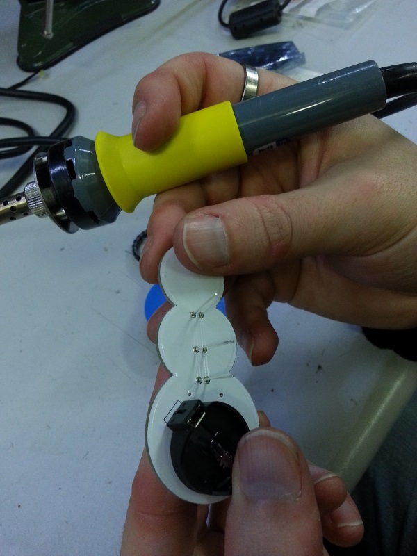
You can now begin to trim the legs with a wire cutter as seen below. Make sure to cut them as short as you can, as to prevent any sharp edges that might snag on your shirt.
Step 4 - Finishing touches
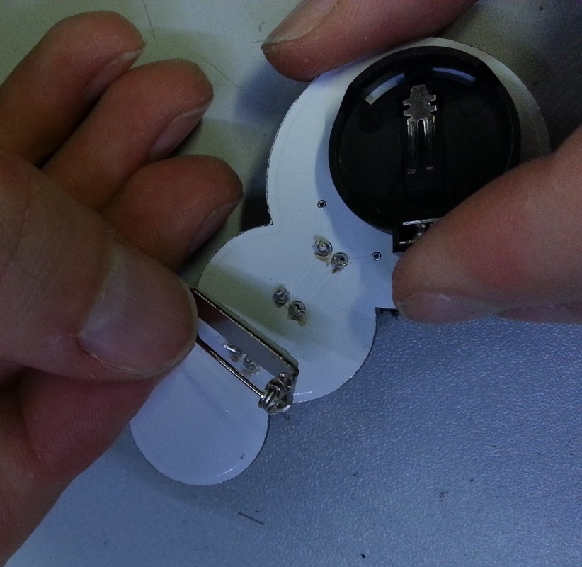
Peel the green label off of the back of the pin, and press it firmly between the top two LEDs on the back of the badge as below.
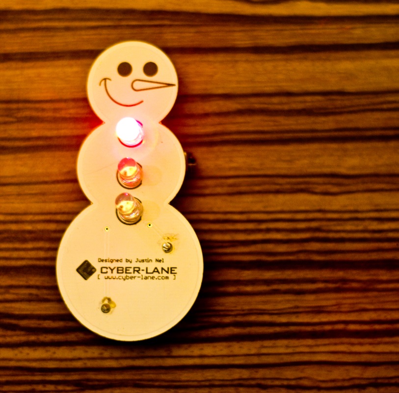
Once the pin is in place, it should look as follows.
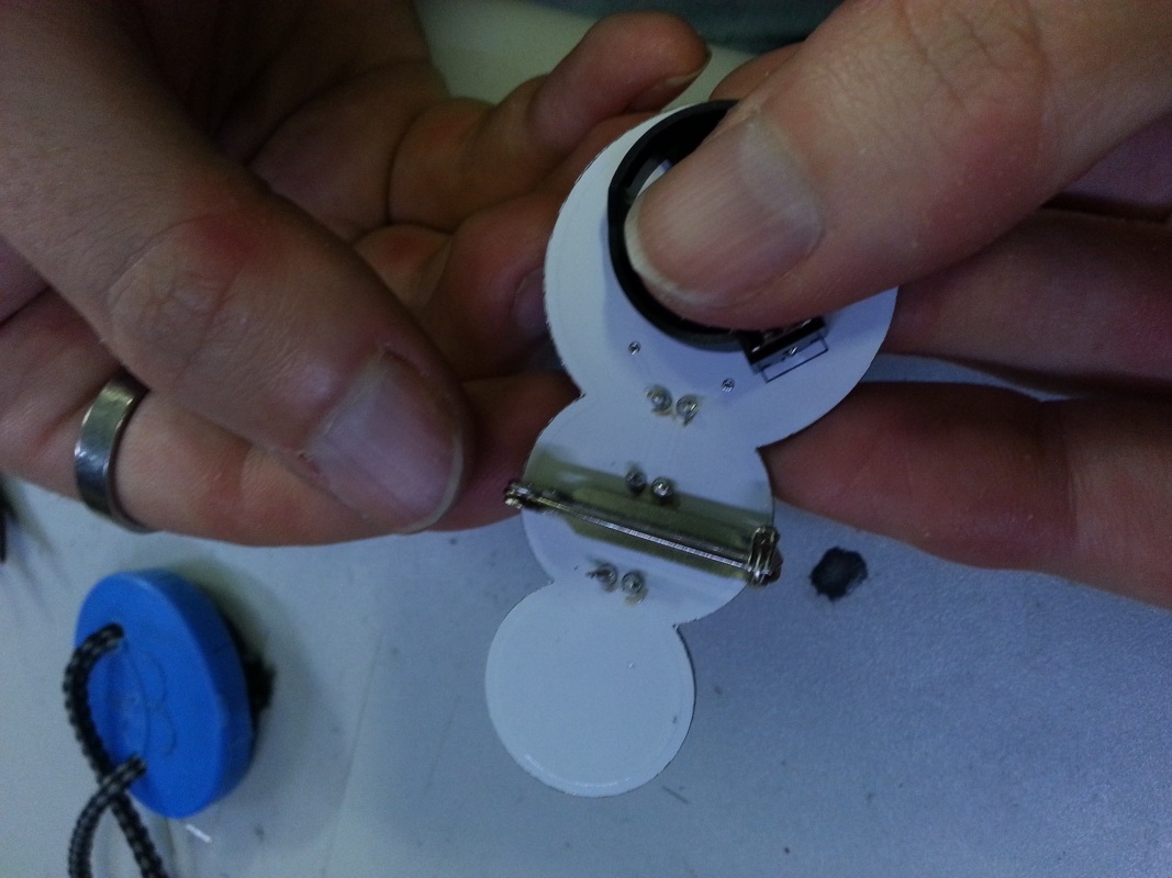
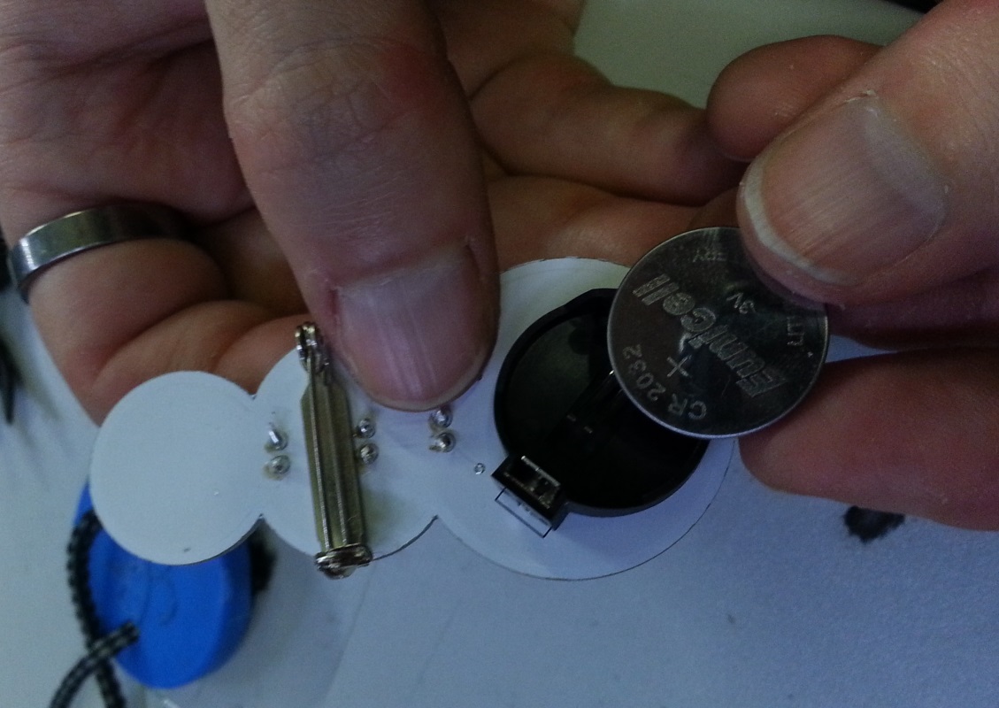
The final step is to fit the battery. The battery should be positive side up (the side with the writing), as seen in the picture below:
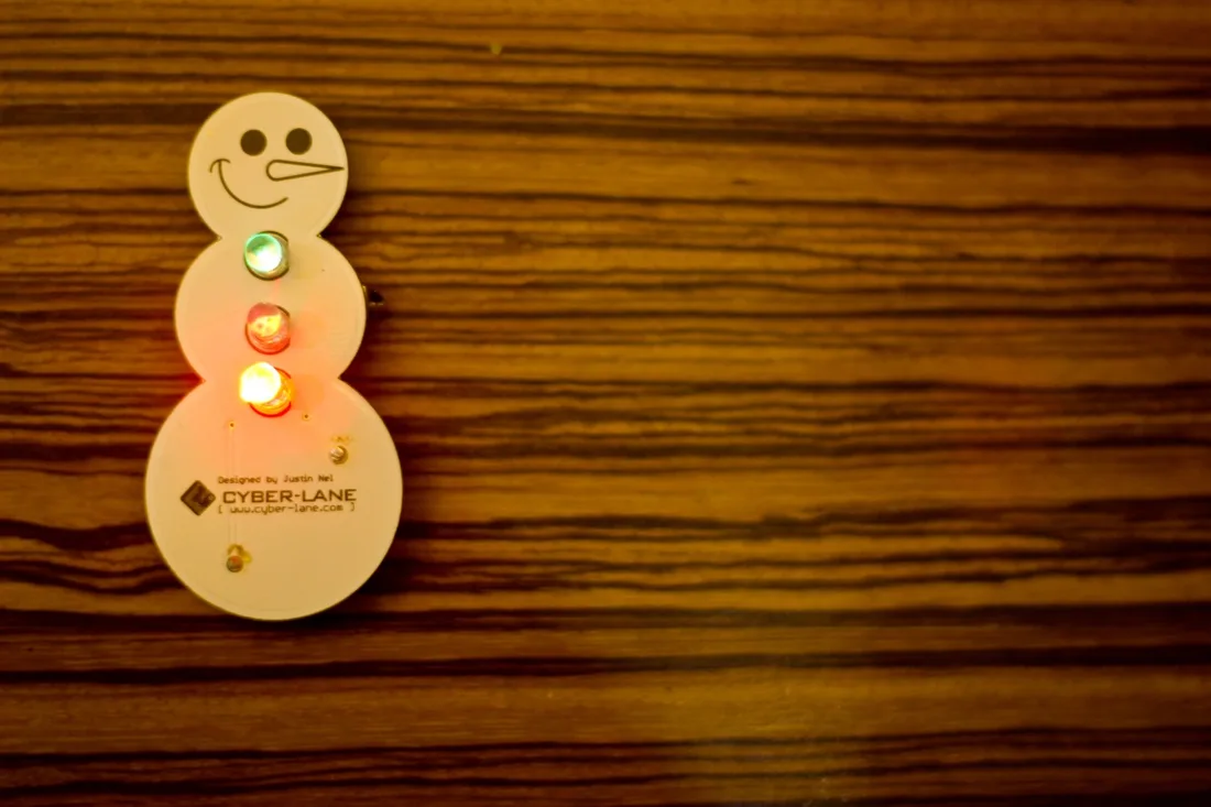
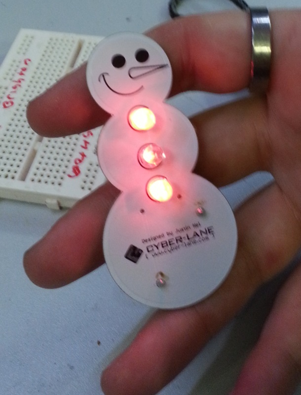
Turn the PCB over and the buttons should be flashing!
Step 5 - Removing the battery
If you want to turn off the badge, you need to remove the battery. On the back of the PCB where the battery holder is sitting, there is a little bit that sticks out to the side.
If you squeeze that bit (you need nails or a pair of needle nose pliers) the battery should release.
You can replace the battery if it dies, or just remove it to stop the LEDs from flashing.
Common Problems
The LEDs are mostly red
If the LEDs are mostly red, and the other colours have faded away, then your batteries need replacing.
Brand new batteries, and the turns flash very dim for a mere moment before stopping
This will happen when one of the LEDs is not wired in correctly, however if you look very closely at each LED you will notice there’s a little slit on the positive side of the LED. You can use this to check your LEDs are in the right way around.