Soldering Is Easy
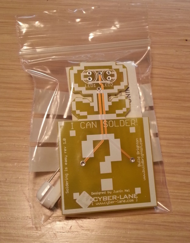
A beginner soldering kit — a light-up flower badge for events and workshops.
Overview · Tutorial · Common Problems
Overview
Tutorial
Step 1 - Your kit
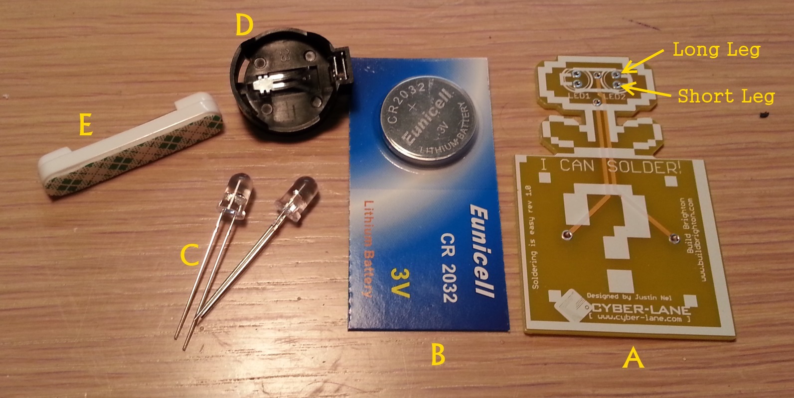
You should have a kit which looks pretty similar to this
Each kit comes with the following pieces:
A) Your badge, which is a Printed Circuit Board (PCB)
B) A CR2032 coincell battery
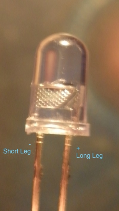
C) 2x LEDs (these will be the ‘eyes’) - one leg is longer than the other: the longer leg goes into the top of each eye, while the shorter goes into the bottom of each eye.
D) A battery holder
E) A sticky pin
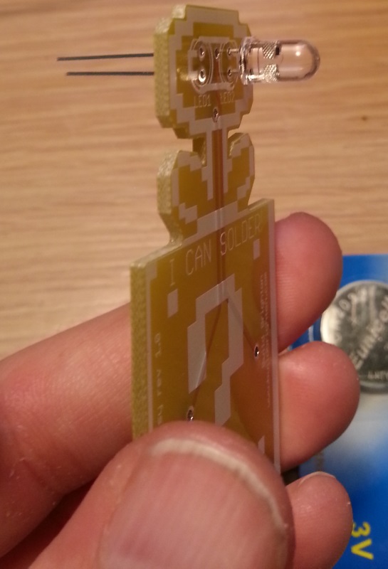
Step 2 - The eyes
You begin by putting the eyes in one at a time: long leg in the top and shorter leg in the bottom. The LEDs might get a little stiff before they’re all the way in, so just give them a bit of a wiggle and they will click right in place.
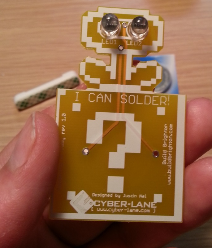
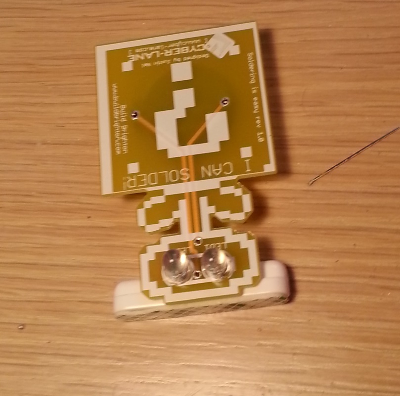
Once both eyes are in, the front of the board should look something like this:
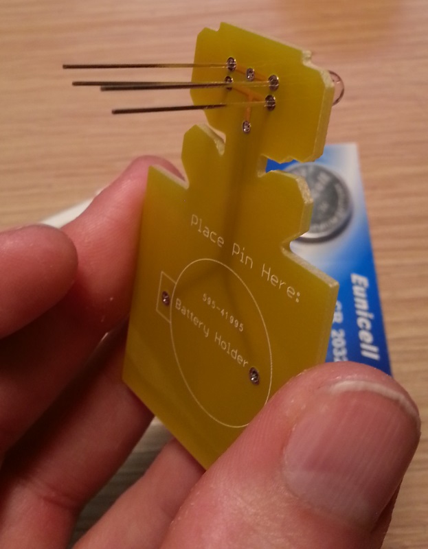
and the back something like this:
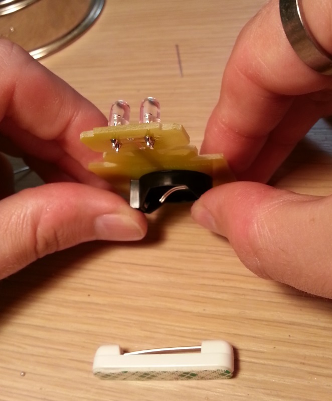
Now we want to have the board face down, and we can use the sticky pin as a pillow to keep everything nice and flat.
Position the PCB onto the pin as such:
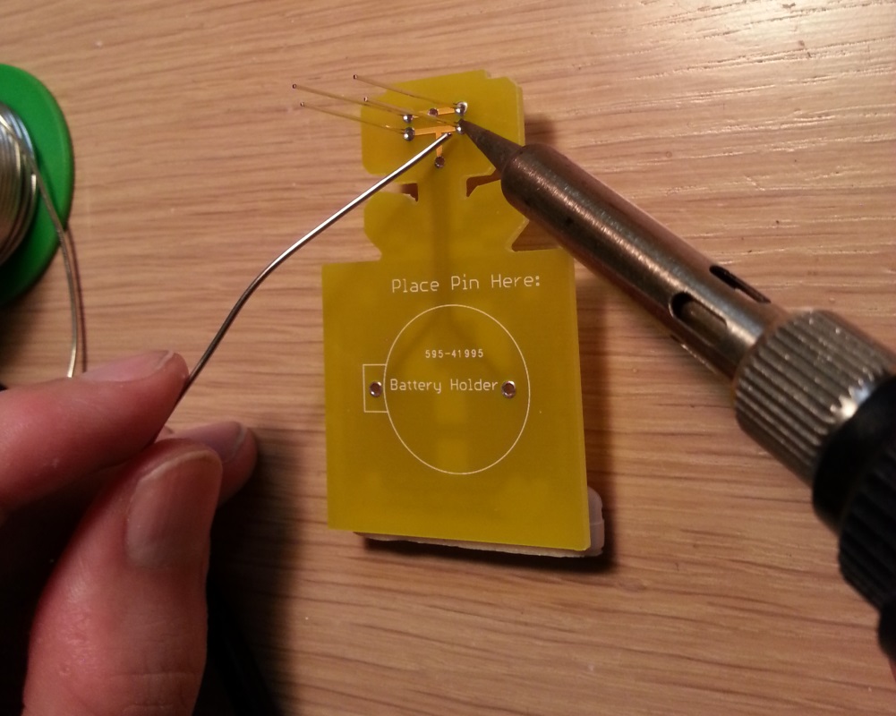
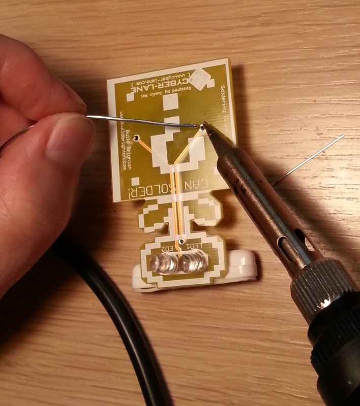
Now it’s time to start soldering. You’ll want to hold the side at the tip of the soldering iron down on one of the silver rings and slowly push the solder into the metal ring near the iron to melt it. Keep pushing the solder until you a nice little solder bubble is formed. If your wire of solder gets stuck, just heat it up with the soldering iron to melt it off.
The PCB is coated in solder resist, so will not melt too easily. However it will eventually wear out and melt if you leave it there for long enough, so try not to hold the iron there for too long.
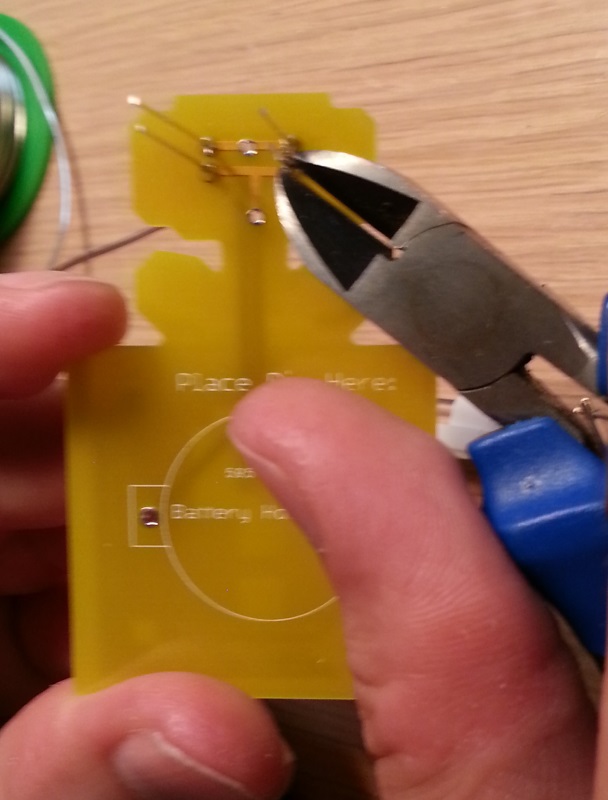
Next you want to trim the legs of the LEDs down to size. Try and cut them as short as you can. If you prefer, you can solder one leg and then trim it, and repeat until they are all complete. Whatever is easier for you.
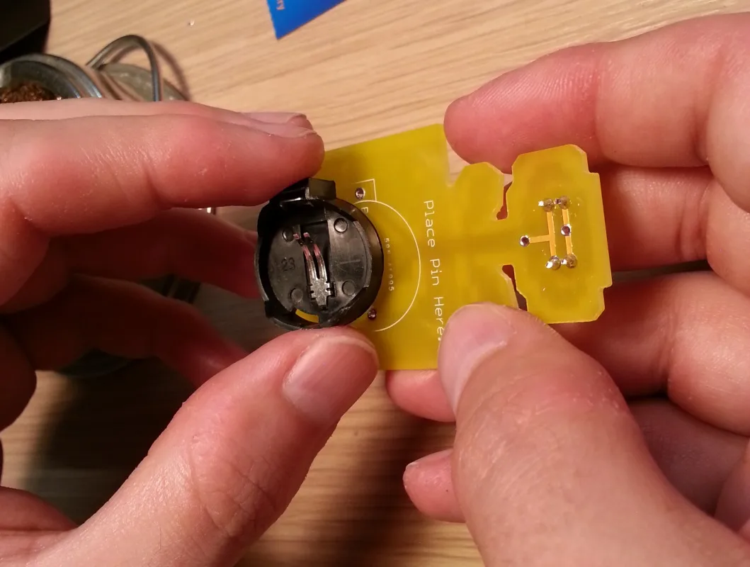
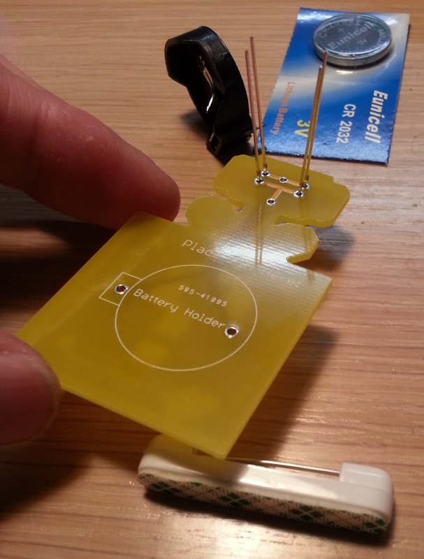
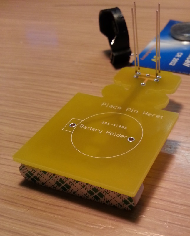
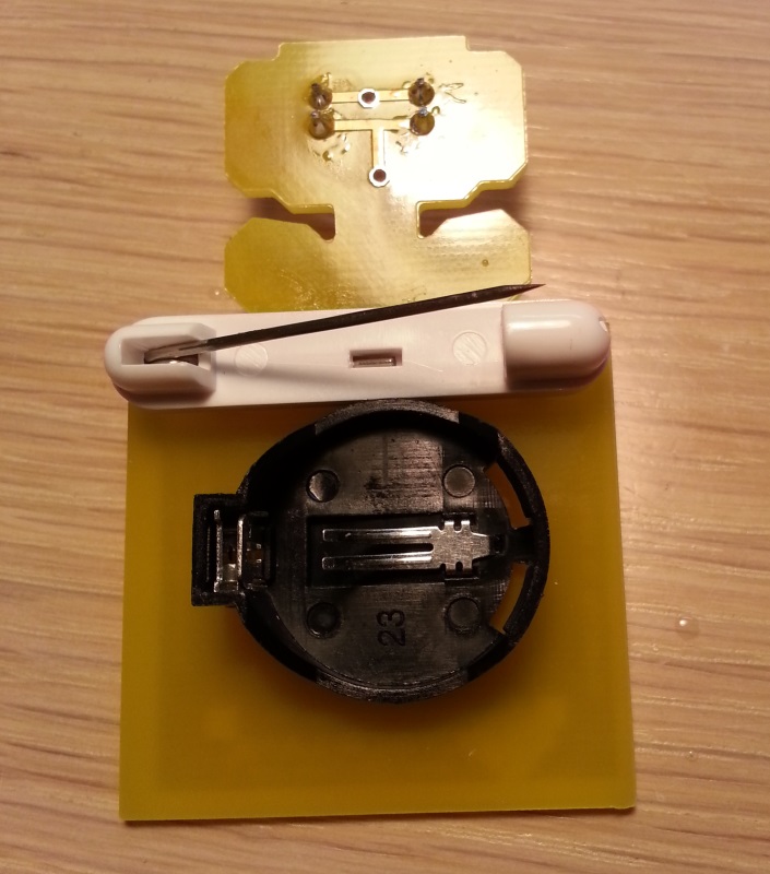
Step 3 - The battery clip
On the back of the PCB there is an outline of the battery holder along with two holes. Match the battery holder with the outilne so the legs of the holder go through the PCB.
Once again we can use the sticky pin as a little pillow to keep everything level.

It should be resting comfortably on the pin.
Just the same as you soldered the LEDs, you will be soldering the battery clips. The only difference this time is that the pins are nice and short so they do not need trimming.
Step 4 - Finishing touches
Peel the green label off of the back of the pin, and press it firmly onto the PCB just above the battery holder. Please ensure that the part where the pin comes out is at the top right, as seen in the picture below:
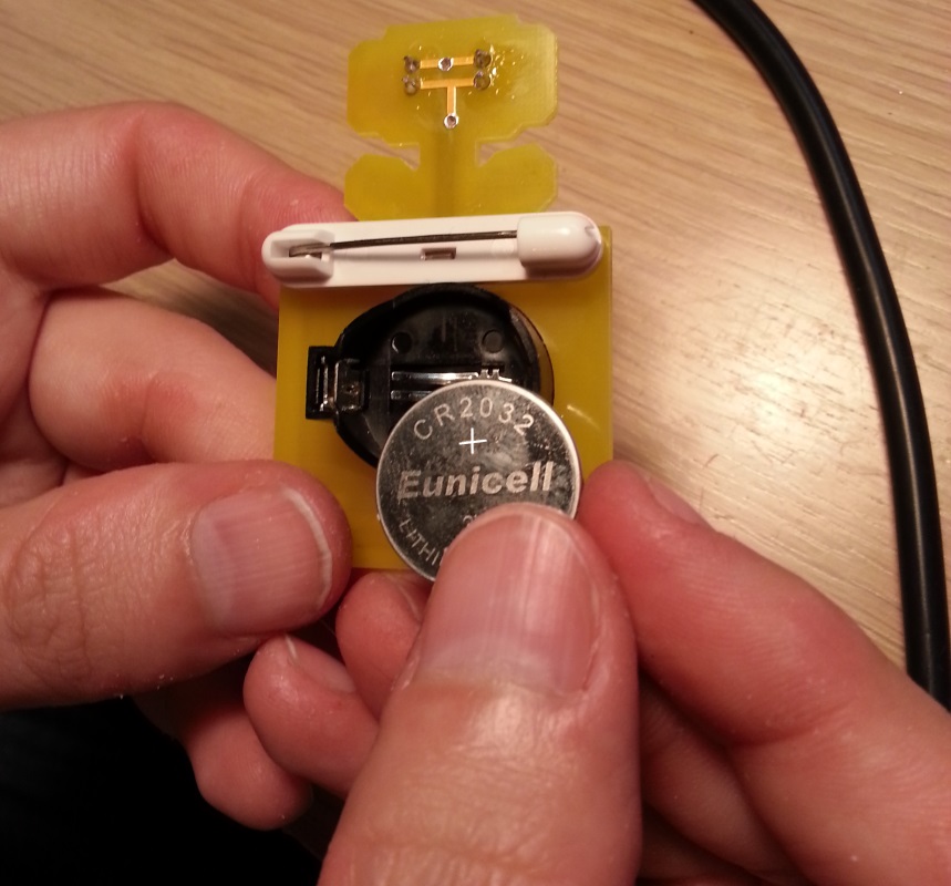
The final bit is to fit the battery. The battery should be positive side up (the side with the writing), as seen in the picture below:
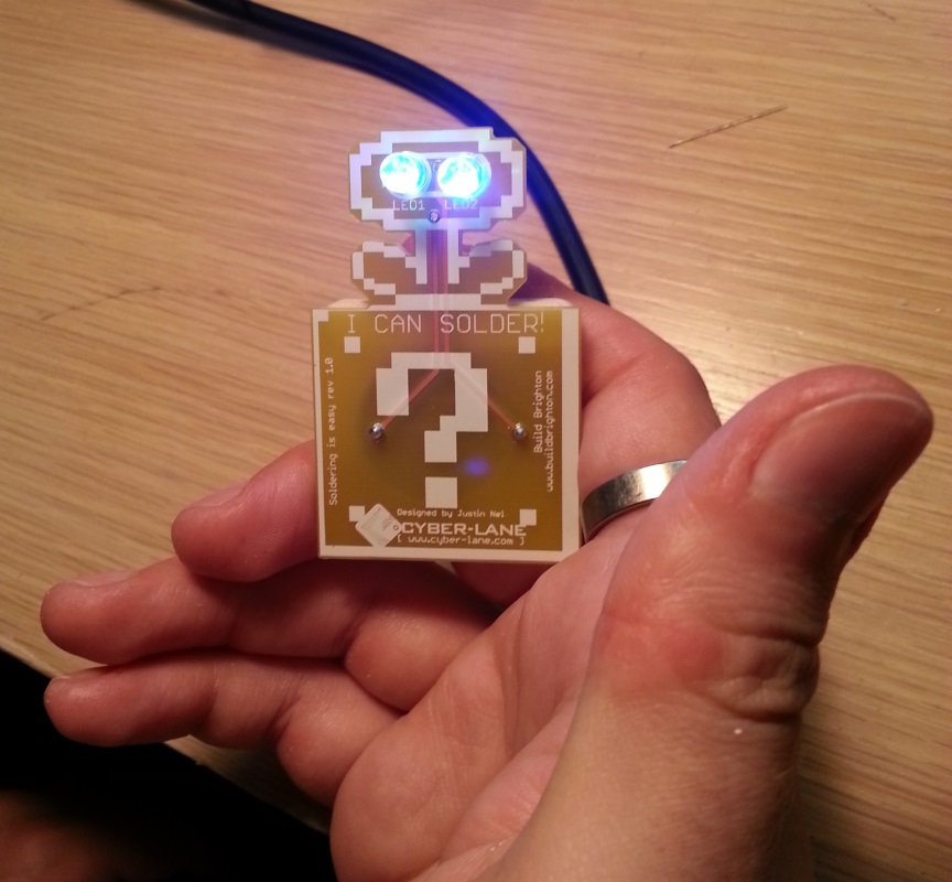
Turn the PCB over and the eyes should be flashing!
Step 5 - Removing the battery
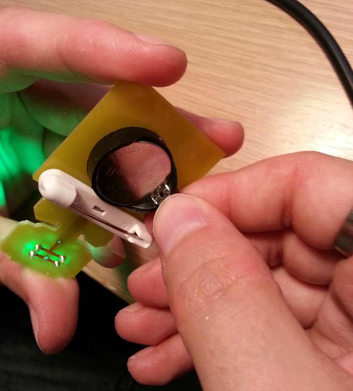
If you want to turn off the badge, you need to remove the battery. On the back of the PCB where the battery holder is sitting, there is a little bit that sticks out to the side.
If you squeeze that bit (you need nails or a pair of needle nose pliers) the battery should release.
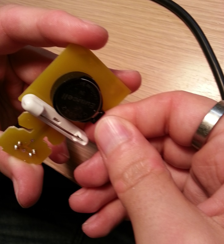
You can replace the battery if it dies, or just remove it to stop the LEDs from flashing.
Common Problems
The LEDs are mostly red
If the LEDs are mostly red, and the other colours have faded away, then your batteries need replacing.
Brand new batteries, and the turns flash very dim for a mere moment before stopping
This will happen when one of the LEDs is not wired in correctly, however if you look very closely at each LED you will notice there’s a little slit on the positive side of the LED. You can use this to check your LEDs are in the right way around.